Go back to News
Tackling fugitive emissions in biogas and anaerobic digestion facilities

|
PVRVs – pressure/vacuum relief valves – are critical safety components on any AD facility. If not properly set, calibrated and serviced, they could be costing you thousands of pounds in lost output and negatively impacting the environment. writes PVRV expert Ewart Cox. |
Biogas mainly consists of methane (40–75%) and carbon dioxide (15–60%). There are also several other trace gases that usually make up less than 2% in volume. These include hydrogen sulphide (H2S) ammonia (NH3), hydrogen (H2), and nitrogen (N2).
Methane and CO2 are greenhouse gases (GHG).
H2S is a colourless and odourless gas that has the foul odour of ‘rotten egg’. However, it’s heavier than air, very toxic, corrosive, flammable, and explosive. This makes it dangerous to the environment, plant infrastructure, and operators, hence all staff working on an AD facility must carry a remote gas monitor when moving around the site as concentrations of around 2 to 5 parts per million can begin to cause nausea.
The ‘trace gases’ in biogas also contribute to the formation of acid rain and air pollution, which adversely impact soils and public health. As well as this ammonia is of growing concern to the government and can arise from the process and its products.
Methane, the main constituent of biogas, is a more potent GHG than CO, by 23 times over its 100-year life, 80 times over the first 20 years. Hence it is the focus of mitigation action against global warming and a great strength of AD is that this potent GHG can be captured from landfill, food waste and manures and converted into a biofuel.
Leaks of any of the gases from the AD process, therefore, pose both an environmental and public health (and relations) concern, hence they are governed by environmental regulations (see box, page 24).
The Environment Agency is becoming increasingly concerned about potential losses and in the absence of data reporting from operators BEIS operate on the assumption of fugitive emissions amounting to 2.5% of output. PVRVs play a critical role in preventing such losses.

PVRVs
There are various types of relief valves that will be deployed on a digester:
Pressure Vacuum Relief Valve units are designed to protect your tank from damage created by over-pressure or excessive vacuum.
PVRVs are the basic/standard model. On a digester, they will usually be found on top of or adjacent to the digesters.
Pressure Vacuum Relief Valve & Flame Arrester are combination units. They are designed to protect your tank from damage created by over-pressure or excessive vacuum and provide protection from externally caused sources of heat and ignition. The result is increased fire protection and safety and prevent an explosion.
Methane, approximately 60% of biogas, is extremely flammable and can form an explosive atmosphere when mixed with air (oxygen). Both have upper (UFL) and lower (LFL) flammability limits, also known as upper and lower explosive limits (UEL/LEL). This emphasises the importance of the DSEAR 2002 Regulations and ATEX zoning on AD plants, which serve to prevent limits from being breached.
Emergency Relief Valves are designed to provide emergency relief capacity over and above that provided by the normal operating pressure relief valve on the tank. The ERV protects the tank against rupture or explosion, which can result from excessive internal pressures caused by an external fire.
Most AD facilities will also feature an emergency flare, to protect the integrity of the plant by safely burning off any surplus biogas. The emergency flare should be fitted with a flame arrester that will contain the flame and prevent blowback from the stack spreading through the pipework.
PRVs serve two principal purposes:
- Digester integrity: PVRVs stop the digester from being catastrophically damaged, either from explosion or implosion, or being lifted from its moorings.
- To reduce fugitive emissions of methane.
Tank Integrity and fugitive emissions
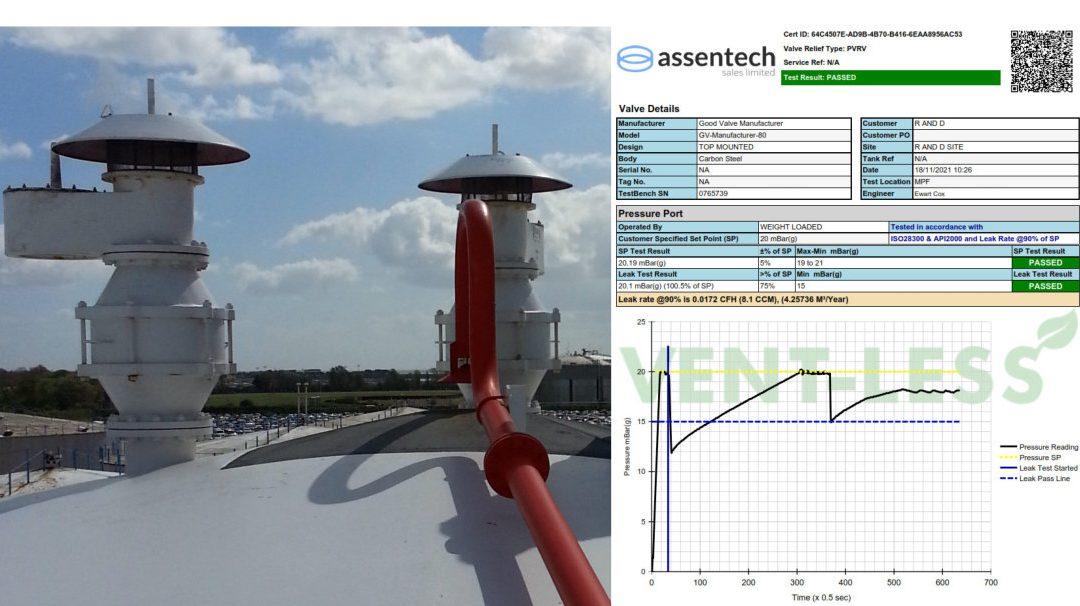
The biggest cause of leakage is from vents that are not designed or tested in accordance with the Standards, API2000 and ISO28300. It is vital that the buyer insists on an individual leak test certificate for both pressure and vacuum ports. The certificate must specify the vent serial number, calibrated equipment used, flow recorded and pressure achieved. A certificate of conformance does not define what functional tests the vent was subjected to.
Concrete and steel digesters are commonly built to withstand up to 30 millibar (mbarg) pressure. On a digester with design pressure at 30mbarg, a PRVR should be set to open (set point) at between 25-27 mbarg so pressure doesn’t exceed 30 mbarg at full capacity. So, best practice would be to run the digester at <75% of the set point, which is 18-20 mbarg depending on the vent size (capacity).
If the PRVR is incorrectly calibrated the digester will either suffer integral damage from overpressure or suffer from running at lower than design pressure. For example, if the set point is lower by 2mbarG the digester will vent methane at around 10m3 per hour, roughly 50kWh, until operating pressure returns. At the current tariff rate that’s a loss of about £5 per hour, £120 per day, £540 per week, £7,000 per annum. By comparison, a routine annual service will cost around £500.
The relevant standards, API2000 and ISO28300, both specify a leak test limit at 75% of set point. PVRVs do not pop open at the set point, they do so only when it is exceeded. So, the recommendation to operate the digester/storage vessel at <75% of the vent set pressure is the only way of guaranteeing the known leak rate from that device.
Some vents are tested at 90% of set point but there is no reference to this in the standards. However, the Standards Committees for both API2000 and ISO28300 are currently reviewing this. It’s unlikely that any changes will come into the standards for 1-2 years and will not likely diminish the 75% test but give a structure for tighter testing if desired.
Tank pressure can be monitored by SCADA, a Supervisory Control and Data Acquisition unit. This is a control system technically described as comprising computers, networked data communications and graphical user interfaces for high-level process supervisory management.

One of its functions is to measure and record the pressure in the tank. However, it will not tell you how much is being vented. To know that, your process management system must record the set level of the PVRV.
Overpressure and underpressure have three primary causes:
- Poor process design and mass balance: part of the AD facility is malfunctioning. Pumps and pipes could have failed or be blocked.
However, SCADA reporting and in-built alarms should alert you to this and automatically stop certain process actions.
A related issue, which could inadvertently have been designed in, relates to pipe and pump processes. If these have not been designed to accommodate the levels of gas output it can cause pressure issues, hence PVRVs will be found throughout the system. Negative pressure is also a serious issue in anaerobic digestion and set points should ensure they have included this consideration in all calculations.
- Maintenance: planned preventative maintenance is not being routinely undertaken, meaning wearing parts are not being monitored. Human error can also lead to issues if the plant is not returned to set points following maintenance. Lack of maintenance is the most common cause of excessive fugitive emissions after poor vent design and operating too close to, or over the set point.
Foam over is the most likely cause of overpressure as it could stick the pallets onto their seat. The set points must never be increased to compensate for poor sealing integrity. A full design review and change to management procedure should be implemented before any set points are increased.
- Biological process control: various feedstocks produce different levels of gas at different speeds. If you’re sourcing feedstock from a variety of sources, there is a risk that biogas production could exceed what is expected, surplus to tank and storage capacity.
PVRV DESIGN CONSIDERATIONS
The leak rate test set out in the Standards (API2000 and ISO28300) influences the basic design of a breather vent. Not all such vents, however, meet this standard of integrity. Price will be a key indicator, often reflecting lower cost machining practices such as drilling and tapping through the body into the inner chamber, which creates a leak path.
More expensive devices will have no such leak paths, where all tapped holes are blind into bosses in the body and O-ring seals separate the internal void from bolt holes in covers. These devices will have been individually tested on a calibrated testing rig, a process that can take 15-20 minutes per vent on manually controlled benches.
Vents with an inherent leak path will not be issued with a leak test certificate when new and this can be an issue for the operator. The Environment Agencyis becoming more aware of the impact of poor quality or unserviced vents
contributing a significant volume of fugitive emissions to the atmosphere. It is now beginning to ask for leak test certificates that are less than three years old. This is definitely an area where ‘The Buyer Beware’ principle applies.
Further to the basic vent body design being key to reduction in expensive losses, the integrity of sealing between pallet and seat ring is vital. As the vent approaches its set point, the pressure underneath begins to lift the pallet. The higher the set point the more weight is added to the pallet assembly.
As previously mentioned, the Standards set a maximum allowable leak rate at75% of set point. Please see the table below for the allowable leak rates.

Pallet Diaphragm Design
The integrity of the seal between the seat ring and pallet is critical to passing the Production Test of both standards (API2000 and ISO28300). The most prevalent mechanism used for tight sealing is an air cushion seat. This has been around since the 1970’s and consists of a recess pressed into the pallet that corresponds with the seat ring diameter. A high quality, semirigid diaphragm in the pallet then flexes into the recess forming a seal. This design allows the pallet assembly to move a small amount while still retaining seat-to-diaphragm tension. The thickness of the diaphragm gets thicker as the pressure/weight increases.
The diaphragm material must be mirror smooth and have no memory. FEPTeflon is a good choice for most applications. This design can often produce compliant sealing rates of up to 90% of set point. This is a different material to FEP Fabric, which has no rigidity and therefore can allow leak paths to evolve. Another material often found in vents is white Teflon, which as it has memory and is very soft is prone to being damaged easily.
Recent developments in vent design have produced metal to metal seating using highly polished and lapped faces. This tends to be on higher settings above 15 mbarg but produces very high integrity sealing up to and over 90% of set point.
The service life of a diaphragm is likely to be between 1-3 years. After a time it will deform into the pallet recess and lose contact pressure on the seat. Scratches and dents in the diaphragm will also affect sealing integrity. Even a human hair sitting across the seat can cause a leakage failure so regular routine maintenance by competent personnel is vital.
The Seat Ring Design
The seat ring must have a machined and sometimes polished flat surface for the diaphragm or pallet to sit on. As with the diaphragm, good condition is essential to efficient operation. Seats can be periodically ground and polished using lapping tools. Any deformations must be taken out. Chips or excessive corrosion will usually mean the vent or seat ring should be replaced.
PVRV Safety Standards
API 2000:2014 and ISO28300:2008 are similar international standards that give guidance on tank venting and venting devices for above ground atmospheric and low-pressure storage tanks in the oil industry. There is no current standard specifically regulating biogas digester vent design but the retention and calibration requirements of a device in the biogas industry are the same as those required in the oil industry. As previously mentioned, both standards require that the manufacturer proves functional operation of each vent manufactured by certifying set point and leak rate.
Also, Engineering Equipment and Materials Users Association (EEMUA). Produces a co-branded document (EEMUA 231 Ed2) in association with SAFed (IMG1 Ed2) which details best practice in storage of hazardous substances below 0.5 mbarg. This is an extremely informative document. EEMUA is an association renowned for expertise on mechanic integrity and asset management. They also run various training courses on many aspects of process and storage safety.
Testing and Verification of Functional Performance
It is a minimum requirement to inspect and record the condition of all assets operating in critical service. Breather vents fall into this category. It is essential that a documented written scheme of examination is followed. In-situ visual inspection will be required every 6 or 12 months or following an overfill or foam over event. Risk assessments must be made at design stage to ensure this can be done safely. One of the most common errors we have seen is where relief devices are mounted directly on top of an isolation valve with no spool between. So when the vent is unbolted the isolation valve becomes unsecured too.
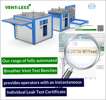
After a period of time, not exceeding 36 months, it will be necessary to remove the vent and conduct a full-service overhaul and functional test. There now exists technology to test breather vent functionality at the customer’s site and produce a calibrated certificate.
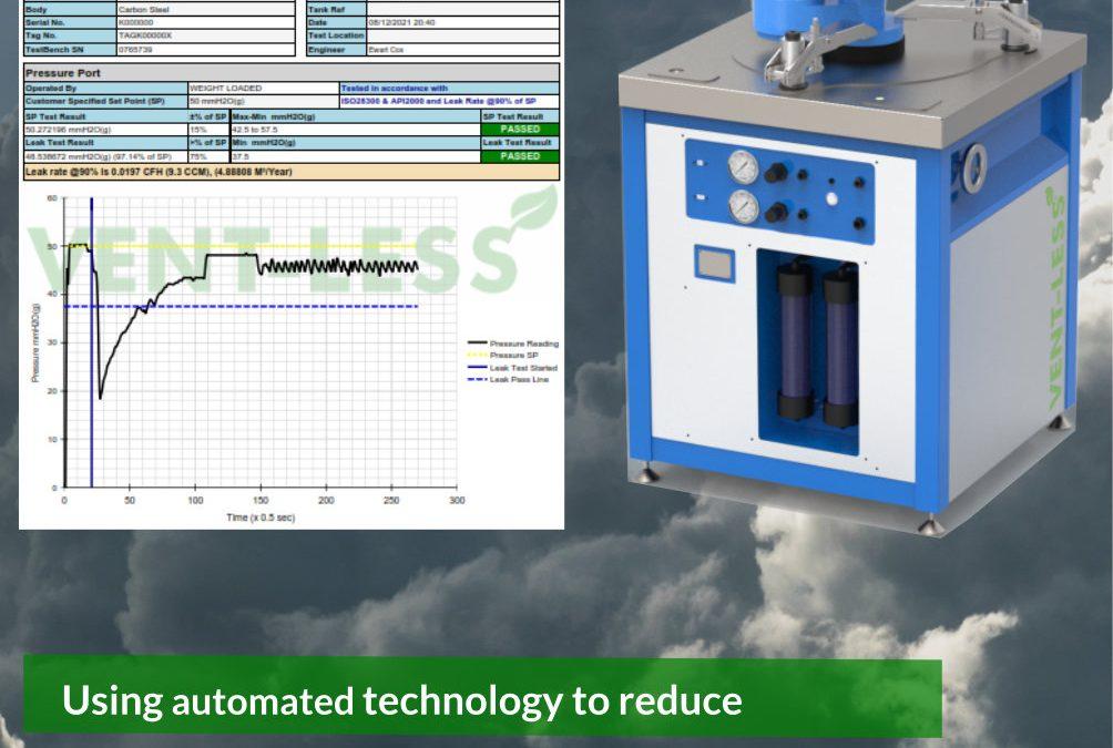
This is a lightweight automated test bench from Assentech that finds the adjusted set point and measures leakage of the device. It is best practice to place the vent onto the bench and run a test ‘as-found’. If the vent passes the test it is up to the Operator whether a full overhaul is necessary. This could lead to longer service intervals.
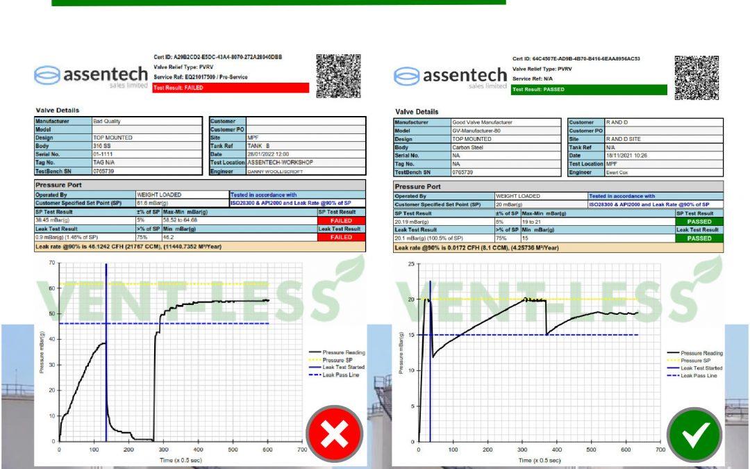
Most vents, however, will fail to retain pressure after 36 months – which explains why the EA is starting to ask for a leak test certificate less than three years old – so it is stripped and rebuilt using new soft goods (ie diaphragms) and checks are made following a second, more detailed written scheme of examination.
Once completed, the vent is tested again and hopefully handed back to the Operator with a full functional operation certificate. Engineers will quickly become accustomed to the brands of vent that will not pass the ‘API’ test and will inform the customer prior to overhauling the device. In this case the vent may be pretested for an initial performance and earmarked for replacement at a future date.
It is essential that testing is done on an automated test bench where the technician has no influence on the outcome so the results stand up to scrutiny as replacement vents can be a significant capital expenditure.
DIGITAL IMAGING

Methane is the simplest alkane and is a colour and odourless gas that can only be seen with technology, such as Optical Gas Imaging (OGI). This technology allows a clear visual representation of the location of a leak using infrared thermal imaging, either on cooled or uncooled detectors. A cooled camera is 10 times more sensitive and can allow a quantification of visual leak.
The image is drawn from the difference in temperature between ambient environment and the gas. What you are seeing is the energy absorption by the gas and in high sensitivity mode it can pinpoint sources of leaks – what are known as ‘weepers and seepers’ – across the system, from tank seams and pipes for instance.
OGI provides an operator to measure, monitor and report the status of the plant. The OGI accessory tablet enables mass emissions rate, concentration, PPM amongst other things to be calculated. It can be rigged to report live. However, this is a technical piece of kit that requires training to operate. It is not just as simple as a point and shoot technique. Hence, camera suppliers, such as FLIR offer a ‘health check’ service through selected partners and service providers. Some AD consultants are starting to adopt the technology.
There are as yet no standards governing OGI performance. NPL, the UK’s National Metrology Institute, develops and maintains the national primary measurement standards is working on one for the EU. NPL is a Public Corporation owned by the Department of Business, Energy and Industrial Strategy (BEIS). Currently, best practice guidance is included in the EU Industrial Emissions Directive.
The Netherlands however are well advanced on delivering a Netherlands Technical Agreement. NTA 8399 provides guidelines for the detection of diffuse VOC emissions using optical gas imaging (OGI). The NTA focusses on portable, passive, optical camera systems that enable volatile organic compounds to be made visible in real time.
This NTA lays down the requirements the IR camera shall meet and the method to be followed to enable reliable statements to be made. On the NTA website it says, “In general, safety, the environment and loss of product are the drivers for applying OGI. OGI can be used in different ways: as part of an LDAR (leak detection and repair) programme; to visualise diffuse VOC emissions of storage tanks; to visualise diffuse VOC emissions that are released while loading operations, and; other applications.”
As alluded to above, leaks can occur from other parts of the facility, such as pipes and tank seams. Studies however has generally recorded these as being <1%, more like 0.01 to 0.02%. Overall, in the absence of data reporting, BEIS operates on the assumption of fugitive emissions being 2.5%. www.nen.nl/en/nta-8399-2015-en-210696
EMISSIONS REGULATIONS GOVERNING AD
Leaks of any of the gases from the ad process pose an environmental and public health (and relations) concern, hence they are governed by the following environmental regulations:
Environmental Permitting Regulations during the standard rules permit review for the ad industry the EA have looked to ensure two key aspects relating to this topic are included.
Biogas storage vessels must be provided with correctly designed and tested pressure/vacuum relief valves. isolating valves must be incorporated to enable inspection and maintenance. the design and installation of PVRVs must be in accordance with recognised standards where possible, for example bs EN ISO 28300:2008.
To mitigate fugitive emissions to air, such as methane from treatment plant and associated infrastructure (for example, pipework, conveyors, lagoons or tanks), you must set up a leak detection and repair (ldar) plan. You must use it to promptly identify and carry out repairs or replacement of plant and equipment.
Clean Air Strategy: Best Available Techniques (Bat) to reduce emissions to air, water and land. bat means the available techniques which are the best for preventing or minimising emissions and impacts on the environment. ‘techniques’ include both the technology used and the way your installation is designed, built, maintained, operated and decommissioned.
Health and Safety Executive There is a raft of guidance and regulations relevant to this topic in the HSE’s ‘Waste & Recycling Sector Workplan (2019 -2020)’, including: transport, safe site, vehicles and drivers; machinery; DSEAR (Dangerous Substances and Explosive Atmospheres Regulations 2002); asphyxiation/confined spaces; and bioaerosols. The HSE also has an array of health and safety regulations that include (not exhaustive):
- The management of health and safety at work regulations 1999
- The workplace regulations 1992 that include the requirement for ventilation
- The personal protective equipment at work regulations 1992
- The reporting of injuries, diseases and dangerous occurrences regulations 1995
Contact us
If you would like to place an order or find out more, please email info@assentech.co.uk, call on +44 1726 844 707, or fill in a contact form here.


Breather vents prevent emissions leaking from storage tanks. View more on breather vents here.
Services:
We offer remote, and in-house, servicing & maintenance of all breather vents to ensure they are working efficiently. Find out more here.


")
