
Bursting disc installation, inspection and replacement
Correct selection can be undermined by poor handling, an incompatible holder, reversed orientation, damaged seating surfaces, misalignment or incorrect tightening. Treat installation and replacement as part of the pressure-safety function—not a routine gasket change.
Safety first: isolate, depressurise, drain or purge and verify the system is safe before work. Competent personnel must use the current instructions for the exact disc and holder.
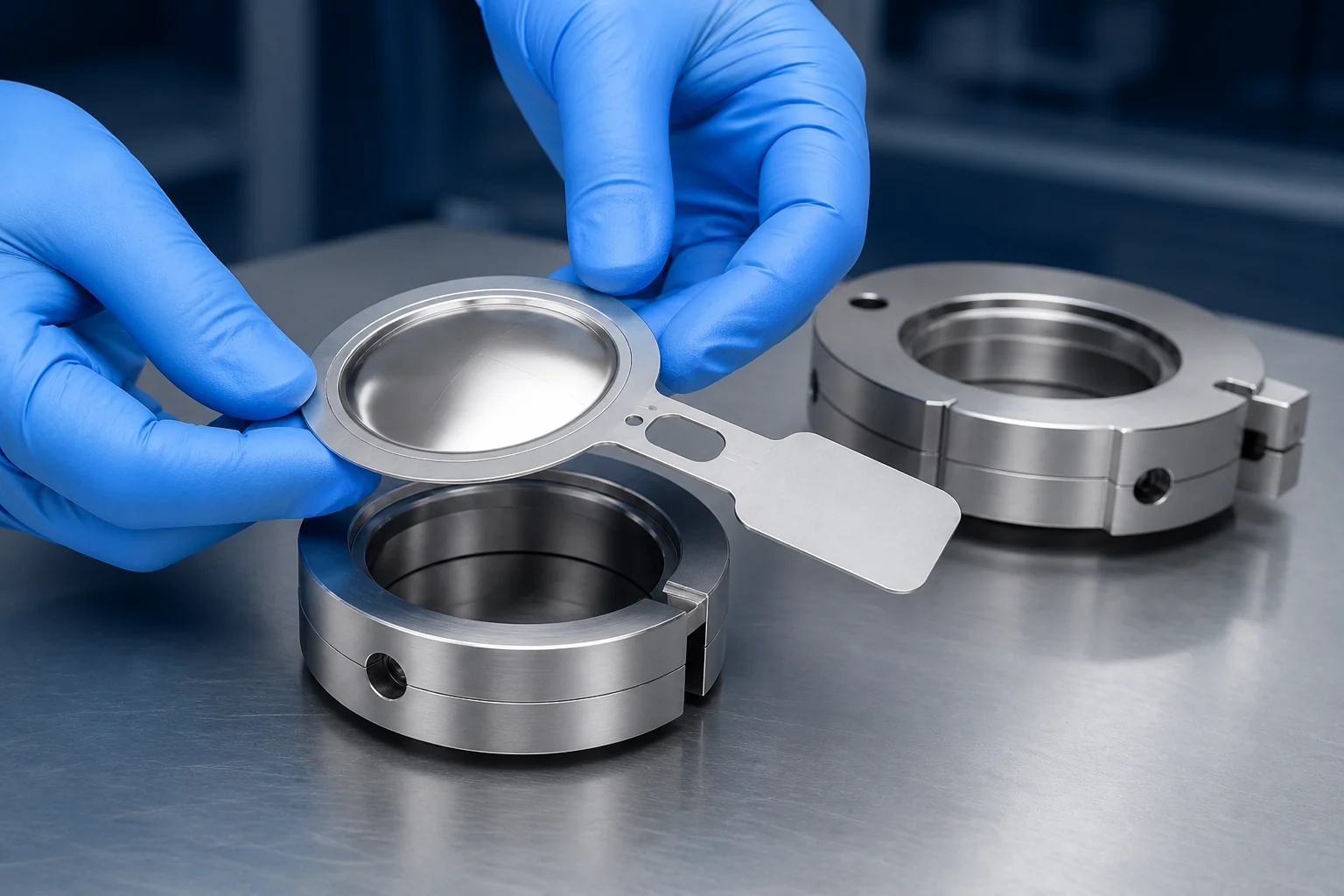
Treat installation as part of the safety function
A rupture disc is manufactured to respond to pressure acting in a defined direction while it is clamped in a compatible assembly. Seemingly small changes to orientation, holder geometry, surface condition or bolt load can affect sealing or burst behaviour.
Do not infer the procedure from a previous disc, another manufacturer or a similar-looking holder. Retrieve the current installation and maintenance instructions for the supplied assembly and retain them in the job pack.
Checks before installing a bursting disc
Make the process safe
Follow site isolation, lockout, depressurisation, draining, purging, gas-testing and PPE requirements. Consider trapped pressure on both sides.
Verify the replacement
Match family, size, material, marked pressure, specified temperature, flow direction, holder and gasket or accessory requirement.
Confirm holder compatibility
Check holder identity, seat design, size, material and condition. Never mix components without explicit manufacturer approval.
Protect the element
Keep it packaged until required. Do not press, flex, scratch or place tools on the pressure-sensitive area. Quarantine suspected damage.
Check faces and alignment
Seats and mating faces should be clean and undamaged. Resolve pipe strain or flange misalignment instead of pulling the joint into place.
Prepare the controls
Have current instructions, approved components, specified gaskets, suitable fasteners and a calibrated torque tool ready.
A manufacturer-led installation sequence
This sequence supports planning. It does not replace the exact product instructions or site procedure.
Ask Assentech for the current installation and maintenance instructions for the exact disc and holder supplied.
Confirm the job pack
Match disc, holder, certificates, instructions and equipment tag. Record the replacement reason and authorisation.
Inspect the assembly
Check seats, bore, flow arrow, alignment, fasteners and any telltale, gauge or indication components.
Orient the disc correctly
Use tag and holder flow markings. Confirm process and vent sides before the assembly enters the line.
Assemble without stressing it
Follow the procedure for the exact holder type and avoid contact with the dome or opening feature.
Tighten as specified
Bring the joint together evenly and apply the documented staged sequence and torque for the assembly.
Reconnect and check
Restore approved indication or monitoring and perform only checks allowed by the instructions and site procedure.
Record and hand over
Capture identity, traceability, orientation, torque, installer, date and observations; update spares and inspection records.
Common causes of early bursting or leakage
More than one factor may be present. Preserve the operated disc and process evidence where safe, then review the complete history.
Reversed orientation
Incorrect process and vent sides can change response or prevent intended operation.
Incorrect tightening
Too little, too much or uneven bolt load can cause leakage, seat damage or unintended stress.
Handling damage
Dents, scratches, bending or impact may weaken the element, and damage is not always obvious.
Holder or flange problems
Wrong holders, damaged seats, deposits, misalignment or pipe strain can compromise performance.
Corrosion or deposition
Process or vent-side media, cleaning chemicals, polymerisation, crystals or solids may attack or obstruct the device.
Cycling or low margin
Pulsation, water hammer, vibration or operation outside the permitted relationship can fatigue a device.
Temperature mismatch
The disc temperature during operation or upset may differ from the value used for specification.
Unrecognised back pressure
Common headers, condensate, closed valves or other relief events can change differential pressure.
Process change
New media, operating modes, cleaning cycles or relief cases can invalidate the approved application basis.
Build inspection into the maintenance programme
A bursting disc has no moving parts, but its installation is safety-critical. Use risk-based intervals rather than a universal replacement claim.
What to do after a disc has burst
Make the event safe
Follow emergency and isolation procedures. Control continued feed, hazardous discharge and backflow.
Preserve evidence
Where safe, retain the disc and tag and record trends, alarms, temperatures, pressures and photographs.
Establish the cause
Determine whether it was a genuine demand or related to damage, corrosion, cycling, temperature or installation.
Check the system
Inspect the relief path and protected equipment for obstruction, reaction effects or discharge damage.
Replace to approved data
Use a new traceable disc compatible with the holder; repeat selection if conditions have changed.
Recommission under control
Complete records, restore indication, verify line-up and obtain approvals before restart.
Burst indication and monitoring
Burst indicators can signal when a device opens, supporting alarms, shutdown logic or operator response. Combined devices may also need a method capable of detecting leakage or pressure between components.
- Define what condition must be detected
- Check electrical and hazardous-area requirements
- Include cabling, barriers and control-system interfaces
- Test the complete loop under the approved procedure
Site and emergency support from Assentech
Send the protected-equipment tag, photographs, process conditions, original documentation and shutdown window through the contact page.
Questions before the joint is closed
Use the exact manufacturer instructions as the controlling document.
Can a removed bursting disc be reinstalled?
Do not reinstall it unless the current manufacturer instructions explicitly permit this. Removal and reclamping can damage or change the element, and its condition may not be verifiable.
Which way round should a rupture disc face?
Follow the process/vent markings on the disc tag and holder and the exact installation drawing. Orientation is design-specific; appearance is not a safe guide.
What torque should be used?
Use only the value, lubrication condition and staged sequence stated for the exact holder, flange and gasket arrangement. There is no safe universal torque.
Can I fit a new disc in an existing holder?
Only when the disc and holder combination is explicitly compatible. Confirm manufacturer, family, seat design, size, material, flow direction and condition.
Why is the new disc leaking?
Possible causes include wrong components, damaged or dirty seats, handling damage, gasket problems, incorrect tightening, flange misalignment, pipe strain or corrosion. Isolate safely and investigate.
Should a disc be replaced after a pressure excursion that did not burst it?
Review the magnitude, duration, temperature, back pressure and manufacturer's guidance. Replace or obtain technical assessment if the permitted conditions may have been exceeded.
How should spare rupture discs be stored?
Keep them in original protective packaging under the environmental conditions specified by the manufacturer, with certificates and instructions linked to the stock record.
What information helps during an emergency call?
Provide clear tag and assembly photographs, holder details, original order or lot reference, medium, pressures, temperatures, event history, current plant status and required date.
Get support for an installation or replacement
Tell Assentech whether the work is planned or urgent and include the protected-equipment tag, disc and holder photographs, process conditions, documentation and shutdown window.